10+ dfd diagram in uml
Biasanya DFD banyak digunakan oleh seseorang yang bekerja di bidang sistem informasi. Diagram ini dipopulerkan oleh Ed Yourdon dan Larry Constantine pada akhir 1970-an dalam bukunya yang bertajuk Structured Design.
Data Flow Diagrams Dfd Example Of Dfd For Online Store Data Flow Diagram Dfd Example Design Data Flow Dfd Library Data Flow Diagram For Restaurant Management System
210 METHODOLOGY 2101 Project Summary The user interacts with the tool using GUI.

. 10 22 DATA FLOW DIAGRAM 221 INTRODUCTION OF DFD A DFD in simple words is a hierarchical graphical model of a system that shows the different processing activities or functions that the system performs and the data interchange among these functions. DFD ERD diagrams etc are drawn for a system in the Final year project. In your level 1 data flow diagram you should include several process nodes major databases and all external entities.
In 1-level DFD the context diagram is decomposed into multiple bubblesprocesses. In the DFD terminology it is useful to consider each function as a process that. It runs only on Windows 10 Anniversary Update or later and so is difficult to use on macOS or Linux.
Download and start right now. ERD Archimate flowcharts DFD wire frames user stories and much more. Data flow diagram DFD adalah ilustrasi alur sebuah sistem.
数据流图DFD- Data Flow Diagram让系统分析者弄清楚做什么的问题其重要性就不言而喻了那么我们怎么画数据流图呢数据流图与系统流程图又有什么区别呢步骤1数据流图里包含的内容数据流图描述的是系统的逻辑模型图中没有任何具体的物理元素只是描绘信息在系统中流动和处理的. Edraw provides with tools that quickly create flowcharts mind maps org charts Gantt charts electrical schematics floor plans infographics etc. Can transform UML EMF models into other models.
17 What is level-0 DFD. It is often used as the basis for data flow diagrams or DFDs as they are commonly known. It is also is known as context level DFD.
Start Creating Beautiful Diagrams. It gives specifications about the entire information system as one diagram which has all the details about the system. For example activity diagrams are a UML subtype that depicts a sequence of activities the system performs.
Yes No Yes No Unknown Unknown Available from the Eclipse M2M project Model to Model. Hingga saat ini DFD banyak digunakan dalam pengembangan. This is very beneficial for both analysis and communication.
Expand the context diagram into a level 1 DFD. Learn from diagram examples and start creating your diagrams online. Draw data flow diagrams can be made in several nested layers.
В отличие от. The Use-Case Diagram is used to prepare present and understand functional. Highest abstraction level is called Level 0 DFD Data Flow Diagram.
Entity Relationship Diagram of Chat Application 18 26. Mind Mapping ER Diagram DFD Flowchart CRUD Traceability Map Requirement Diagram and Requirement table. в UML 1x диаграмма кооперации collaboration diagram диаграмма на которой изображаются взаимодействия между частями композитной структуры или ролями кооперации.
28 Entity Relationship Diagram Figure 9. A Sequence B Collaboration C Clas D Object Answer. It can be used for creating infographics which is used for data visualization.
For example an inventory software used in a retail shop will have a database that monitors elements such as purchases item item type item source and item price. It permits you to specify and generate code in C Java Idl Php Python and MySQL. In this level we highlight the main functions of the system and breakdown the high-level process of 0-level DFD into subprocesses.
A data-flow diagram has no control flow there are no decision rules and no loops. The single process node of your context diagram doesnt provide much informationyou need to break it down into sub-processes. The tool provides an online live Demo.
25_____diagram in UML shows a complete of a modeled system at a specific time. Software developers use Unified Modeling Language to map the components of a system and how they relate. UML 2 Compatible with UML 2x standard metamodel and diagrams.
Search Edraw site for more information. Depending on the type of UML diagram they may focus on the structural design or dynamic behavior of a system. Provides API and Plugins RTF HTML Export.
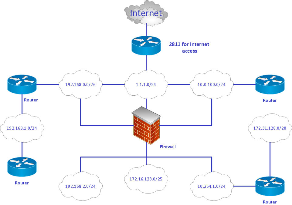
Define Data Flow over your DFD Define Data Flows over the organization Data Flow Diagram. A data-flow diagram is a way of representing a flow of data through a process or a system usually an information systemThe DFD also provides information about the outputs and inputs of each entity and the process itself. 29 Data Flow Diagram Figure 10.
2-level DFD goes one step deeper into parts of 1-level DFD. Specific operations based on the data can be represented by a. Free UML tutorials database tutorials for uml modeling use case modeling requirements capturing ERD DFD BPMN round-trip engineering and more.
The GUI Operates in two forms Contacts Forms and Chat forms. I want a relationship between er diagram and uml diagram. Learn about UML BPMN ArchiMate Flowchart Mind Map ERD DFD SWOT PEST Value Chain and more.
In order to help you with that Visual Paradigm enables you to reverse your Java source code into UML sequence diagram so that you can gain a better understanding of Java source code by reading diagram instead of looking to a possibly thousand lines of source code. SeaSponge SeaSponge is an accessible web-based threat modeling tool. Data Flow Diagram Levels.
Dfdデータフロー図 機能情報関連図 データフローダイアグラムとは情報システムの設計時などに作成される図の一つで要素間のデータの流れを表した図データがどこで発生しどこからどこへ運ばれどこへ出力保管されるのかを図示することができる. Data Flow Diagram of Chat Application 19 27. A context diagram is a top level also known as Level 0 data flow diagram.
用途などに応じて微妙に表記法の異なる10以上の記法が考案され様々な用途に使用されている 中でも有名なものとして米国立標準技術研究所 NIST が規格化したIDEF1x記法IDEFICAM Definition LanguageジェームズマーティンJames Martin氏が考案し. Common Mistakes of Use Case DiagramsGraphically Represented inheritance in use case diagram. BOUML is a UML diagram designer which is programmed in Qt and C.
It only contains one process node Process 0 that generalizes the function of the entire system in relationship to external entities. Class Object Use Case Component Deployment Composite Structure Sequence Communication Statechart Activity and Profile Diagram. Additional Diagrams Support to create Entity-Relationship Diagrams ERD Data-flow Diagrams DFD an.
The Use Case Diagram is a UML Diagram where the each use-case specifies the behaviour expected from software from the perspective of end-user and relation as well as provides brief overview for different components concerning interaction between use-case actors and systems.

I Will Design Uml Diagrams Process Mapping And Mockups Through Flowcharts In 2022 Process Map Software Engineer Mind Map
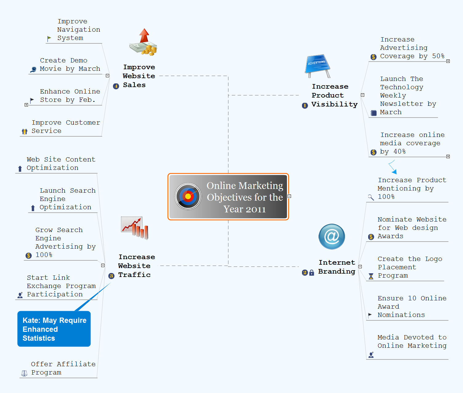
Gantt Chart Examples Gantt Chart Examples Online Marketing Objectives Marketing Launch Schedule Sample

Structured Analysis Wikiwand
Database Flowchart Symbols Flow Chart Symbols Basic Flowchart Symbols And Meaning Database Flowchart Symbols
What Are The 10 Business Process Modelling Techniques Explained With Examples Quora

Structured Analysis Wikiwand
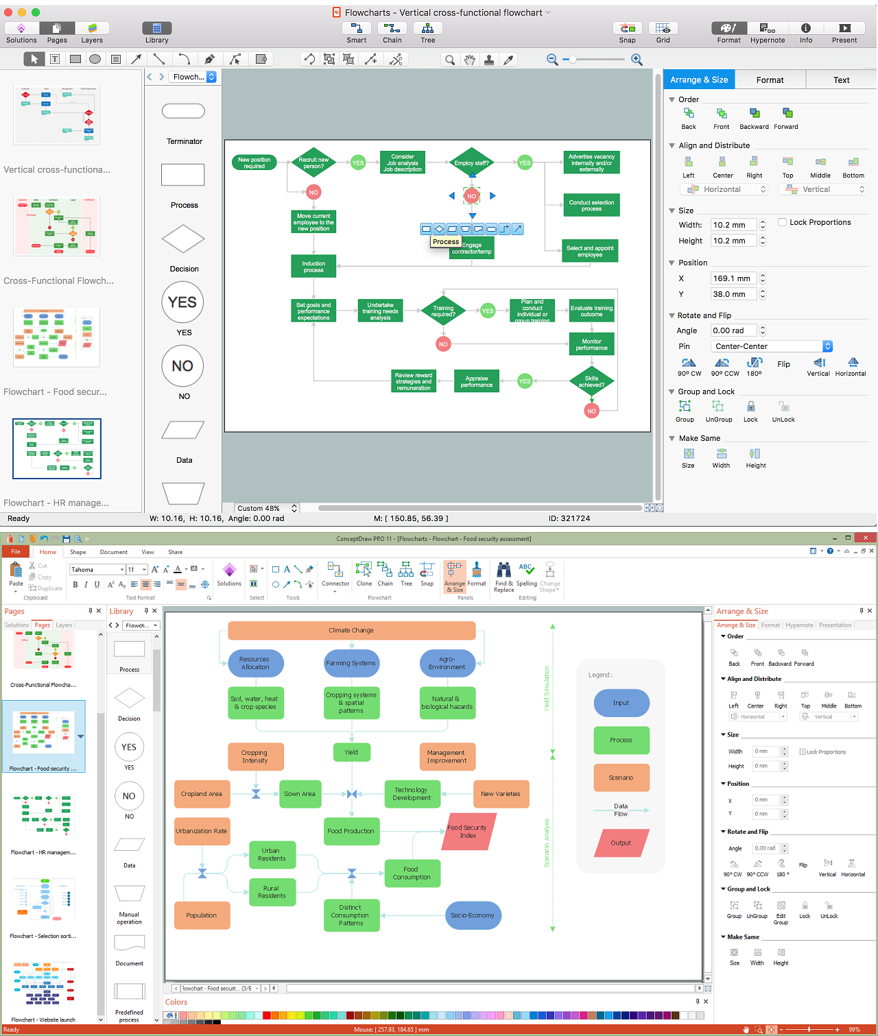
Creating A Flow Diagram To Visually Explain A Process
What Is The Difference Between A Sequence Diagram And An Activity Diagram Quora

Event Partitioning Wikiwand

Pin On Flowchart Templates Examples
How Do We Read Cardinality In A Uml Diagram Or In E A Diagram Quora

Basic Flowchart Symbols And Meaning Types Of Flowcharts Flowchart Components Difference Between Workflow And Flowchart
Creating A Flow Diagram To Visually Explain A Process

13 System Analysis Ideas Use Case Class Diagram Flow Chart
Creating A Flow Diagram To Visually Explain A Process

Technical Flow Chart Example Flowchart Components Technical Flow Chart Workflow Diagram Examples

Looking To Download Root Cause Analysis Template Then You Are At The Right Place These Templates Help You Analyze Analysis Report Template Problem Statement